2026 How to Configure a Juniper EX Series Network
Configuring a Juniper EX Series Network in 2026 requires more than connecting switches and assigning IP addresses. It demands a clear understanding of business goals, physical layouts, security boundaries, and future growth. John Gage’s well-known statement, “The network is the computer,” still captures this reality. Every EX switch affects application performance, user access, and operational continuity.
This guide approaches Juniper Ex Series Network configuration from a practical engineering perspective. It considers Junos OS versions, Virtual Chassis design, VLAN segmentation, trunk links, PoE budgets, uplink capacity, and management access. A small office may need only two EX switches, while a campus network may require redundant distribution paths and carefully planned fiber connections. Test every assumption.
Reliable deployment begins before the first command. Record switch models, serial numbers, interface maps, IP ranges, and required firmware. Use commit check before committing changes. Keep a rollback plan. Verify LLDP neighbors, spanning-tree behavior, DHCP delivery, and endpoint authentication after each major step. These details often reveal problems that a successful ping cannot show.
The process is not flawless. Documentation may be incomplete. Older devices may behave differently than expected. That is why staged testing matters. A temporary lab switch, a console cable, and a saved configuration can prevent a rushed outage. Monitoring should also continue after installation, because stable performance on day one does not guarantee reliable operation later. This 2026 guide explains the configuration path, common mistakes, and practical checks that help make a Juniper Ex Series Network secure, manageable, and easier to improve.
Understand the Juniper EX Series Hardware and Network Requirements
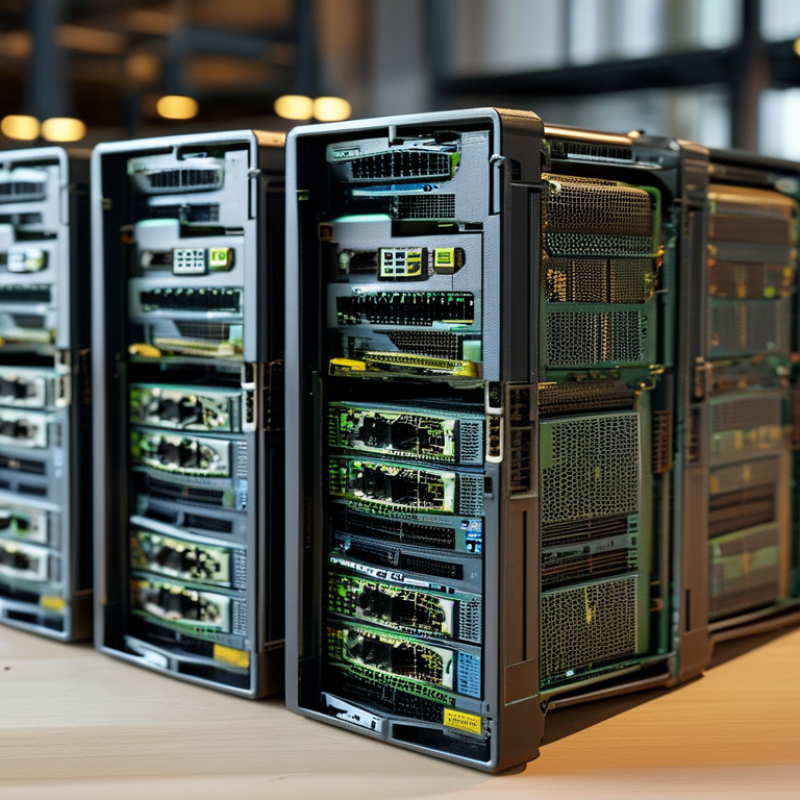
Before configuring an enterprise access switch, inspect the hardware like a small power system. Confirm the model, port speeds, uplink modules, power supplies, airflow direction, and rack depth. A 24-port copper unit cannot replace a 48-port fiber design without trade-offs. Check transceiver compatibility carefully. A connector may fit while its optics remain unsupported. I once overlooked rear clearance and created a maintenance problem. That mistake was avoidable.
Network requirements should be written before commands are entered. Document VLANs, management addresses, gateway details, routing needs, DHCP dependencies, authentication, monitoring, and expected PoE demand. Reserve address space for management and label every cable at both ends. Calculate uplink capacity from real traffic, not port counts alone. Voice devices, cameras, and wireless access points can create uneven bursts. Use redundant uplinks where failures affect operations, but verify loop protection and spanning-tree behavior. Test software compatibility with installed modules and endpoints. Familiar templates can hide wrong assumptions.
Tips: Keep a pre-install checklist with photographs, serial records, power readings, and measured cable lengths. Use a temporary test VLAN before production deployment. Record failed tests too; they often reveal weak requirements. Review the plan with someone who did not build it. Fresh eyes help.
2026 Enterprise Access-Switch Network Configuration
Common Ethernet link rates used when matching switch port capabilities to endpoint, access-point, server, and uplink requirements.
The values show standardized nominal link speeds in gigabits per second. Actual application throughput is lower because of protocol overhead, traffic patterns, hardware capacity, and network design.
Prepare Console Access and Perform the Initial Device Setup
Preparing console access makes the initial setup of an enterprise switch safer and more predictable. Use the supplied console cable with a tested laptop and terminal program. Set the terminal session to 9600 baud, 8 data bits, no parity, one stop bit, and no flow control. Confirm the console prompt before changing settings. A wrong cable can look like a software failure.
Log in with the factory credentials defined in the current device guide, then replace them immediately with unique administrator credentials. Set a clear hostname, management address, subnet mask, default route, time zone, and reliable time source. Enable secure remote management only after local access works. Review the configuration before committing it, and save a backup outside the switch. In practice, I once missed the management VLAN and temporarily lost remote access. That mistake reinforced the value of testing from a separate workstation.
Tips: Label both cable ends. Keep a written console record. Capture the original configuration before edits. Test the management address with a direct connection, then verify remote access from the intended administration network. Remove unused services and ports, but document every change. A rushed security cleanup can interrupt operations, so apply changes during an approved maintenance window. Check interface status, link speed, and error counters before connecting production devices. Recheck everything.
Configure VLANs, Interfaces, and Layer 2 Switching
A reliable Layer 2 design starts with clear VLAN roles. Create separate networks for users, voice devices, management, and guest access. Give each VLAN a meaningful name and documented purpose. This makes troubleshooting faster when a device loses connectivity.
Assign edge ports as access interfaces, and place only the required VLAN on each port. Use trunk interfaces between switches, allowing an explicit VLAN list instead of every available VLAN. Keep it simple. I once left an unused VLAN permitted on a trunk, and a later change caused confusing broadcast traffic. That mistake reinforced the value of narrow configurations.
Enable loop protection and select a predictable spanning-tree root for the switching domain. Disable unused interfaces, label active ports, and record connected devices. Before applying changes, save the current configuration and test one interface. Afterward, verify VLAN membership, trunk status, MAC learning, and interface errors. A small test laptop can confirm whether the expected address range and gateway are reachable. Do not rely on link lights alone. They show physical activity, not correct switching behavior.
For management access, use a dedicated management VLAN and restrict it to approved administration paths. Review the design after deployment. Some assumptions will be wrong. A port may connect to a phone, access point, or small unmanaged switch, so field checks still matter.
2026 How to Configure a Juniper EX Series Network - Configure VLANs, Interfaces, and Layer 2 Switching
| Configuration Area |
Example Setting |
Recommended Value |
Purpose |
Validation Check |
| Management VLAN |
VLAN ID 10 |
10.10.10.0/24 |
Separates switch administration traffic from user and device traffic. |
Management gateway responds and only approved administrators can reach it. |
| Employee VLAN |
VLAN ID 20 |
10.10.20.0/24 |
Provides network access for standard wired workstations. |
A test client receives an address from the correct subnet. |
| Voice VLAN |
VLAN ID 30 |
10.10.30.0/24 |
Keeps real-time voice traffic logically separate from data traffic. |
Voice devices register and use the dedicated address range. |
| Guest VLAN |
VLAN ID 40 |
10.10.40.0/24 |
Provides restricted access for visitors and unmanaged endpoints. |
Guest clients reach the internet but not internal private networks. |
| IoT VLAN |
VLAN ID 50 |
10.10.50.0/24 |
Isolates cameras, sensors, printers, and other embedded devices. |
Only explicitly permitted services are reachable from this segment. |
| Access Interface |
Ports 1–20 |
Single untagged VLAN; edge protection enabled |
Connects end-user devices that do not carry multiple VLAN tags. |
The interface forwards only the assigned access VLAN. |
| Trunk Interface |
Ports 21–22 |
Tagged VLANs 10, 20, 30, 40, and 50 |
Carries multiple VLANs between switches and upstream routing devices. |
Allowed VLAN lists match on both ends of the link. |
| Native VLAN |
VLAN ID 999 |
Unused and administratively blocked |
Reduces exposure from untagged frames on trunk links. |
No production endpoint is assigned to this VLAN. |
| Layer 2 Learning |
MAC address table |
Dynamic learning enabled |
Allows frames to be forwarded only toward the learned destination port. |
The source MAC appears on the expected interface and VLAN. |
| Spanning Tree |
RSTP |
Enabled on all switching VLANs |
Prevents Layer 2 loops while providing faster recovery than classic STP. |
One root bridge is elected and redundant paths are placed in a safe state. |
| Broadcast Control |
Storm protection |
Rate limits for broadcast and unknown-unicast traffic |
Limits the impact of loops, faulty devices, and excessive flooding. |
Counters remain below configured thresholds during normal operation. |
| Unused Interfaces |
Ports 23–24 |
Disabled or isolated |
Prevents unauthorized connections to inactive physical ports. |
Link status remains down unless the port is intentionally enabled. |
| Uplink Redundancy |
Two uplink members |
Aggregated logical link |
Improves availability and can increase available uplink capacity. |
Both physical members are active and use consistent settings. |
| Verification |
Operational checks |
VLAN, interface, MAC, and STP status review |
Confirms that the intended Layer 2 design is active and stable. |
No unexpected VLANs, blocked uplinks, errors, or MAC flapping are present. |
Set Up Layer 3 Routing, Management Access, and Security
Layer 3 routing begins with a clear IP plan. Create separate VLANs for users, voice devices, servers, and network administration. Assign each VLAN a routed interface and a documented gateway address. Keep the management subnet separate. This reduces exposure during troubleshooting and limits accidental access between departments. Add static routes only when the topology is small. Larger environments usually need a dynamic routing protocol, with authentication enabled between neighbors.
Use a dedicated administration address and permit access only from approved support networks. Secure remote sessions with SSH keys, strong local credentials, and centralized authentication when available. Disable unused services and restrict management protocols through an access control list. SNMPv3, encrypted logging, and reliable time synchronization improve audit quality. Test each control from an ordinary user VLAN, not only from the administrator’s laptop.
Security rules need practical validation. Confirm that users cannot reach switch management interfaces, while approved engineers can connect during an outage. Check routing tables, interface states, and log timestamps after every change. In lab work, I once allowed an overly broad management rule because the test laptop had the wrong address. The configuration looked correct. It was not. Review source ranges carefully, save a backup, and document the reason for every exception. Test from another subnet.
Verify Connectivity, Save the Configuration, and Plan Maintenance
After configuring a campus switch, verify connectivity from the cable outward. Check interface status, link speed, VLAN membership, gateway reachability, and DNS resolution. Test one wired client in each access segment. Then run ping and traceroute to the gateway and a permitted internal service. Record timestamps, source ports, packet loss, and latency. A green link light proves little. It does not prove correct forwarding.
Save the configuration only after testing passes. Capture the active configuration, compare it with the approved baseline, and store a dated copy in access-controlled version storage. Include the operator, change ticket, software release, and rollback file. The 2024 Annual Outage Analysis found that 54% of serious outages exceeded $100,000 in total impact. A missing configuration backup can make a small fault expensive. I still distrust “successful” commits when no independent device check follows.
Plan maintenance around traffic patterns, not convenience. Define a change window, pre-check commands, console access, rollback triggers, and an owner who watches alerts. Re-test after reboot, failover, and power restoration. The 2024 Data Breach Investigations Report attributed 68% of breaches to the human element. That figure supports peer review, separation of duties, and short runbooks. Review logs within 24 hours, then schedule firmware and configuration audits quarterly. Quarterly may be too slow for unstable sites; adjust it after evidence, not habit.